A Series Of Problems Of DCDC In Electric Vehicle Electrical System
DC/DC Converter, As A Very Important Part Of Electric Vehicle Power System, One Of Its Important Functions Is To Provide The Required Power For Power Steering System, Air Conditioner And Other Auxiliary Equipment. The Other Type Is In The Composite Power System, Which Is Connected In Series With The Super Capacitor To Adjust The Power Output And Stabilize The Bus Voltage.
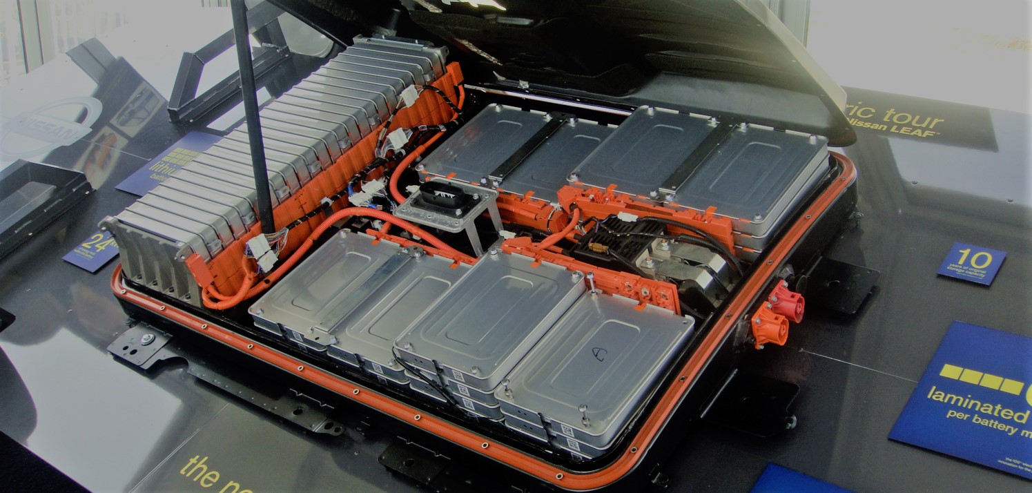
To Supply Power To The Vehicle Electrical, The Location Of The DCDC In The Electrical System Of The Electric Vehicle Is Shown In The Figure Below. Its Electric Energy Comes From The Power Battery Pack, And The Place Is To Supply Power To The On-Board Electrical Appliances.
The Position Of The DCDC Used In Conjunction With The Supercapacitor In The Vehicle Power Supply Is Shown In The Figure Below. It May Appear In The Positions Shown In Figures (B), (C), And (D), And (B) Is More Widely Used. A Form Of.
- DC DC Classification And Working Principle
1.1 Isolated And Non-Isolated
What Is Electrical Isolation?
A Paragraph From Baidu: Electrical Isolation Is The Electrical Isolation Of The Power Supply And The Electrical Circuit, That Is, The Electrical Branch Circuit Is Isolated From The Entire Electrical System, Making It An Electrically Isolated, Independent Ungrounded Safety System To Prevent The Risk Of Indirect Electrocution In The Event Of An Exposed Conductor Faulty Live. After Electrical Isolation Is Achieved, There Is No Direct Electrical Connection Between The Two Circuits. That Is, The Two Circuits Are Insulated From Each Other. At The Same Time, It Is Necessary To Ensure That The Two Circuits Maintain The Relationship Of Energy Transmission. The Main Function Of Electrical Isolation Is To Reduce Mutual Interference Between Two Different Circuits And Reduce Noise.
The Non-Isolated Two-Way DCDC Has A Relatively Simple Structure, Each Component Is Directly Connected, There Is No Additional Energy Loss, And The Work Efficiency Is Relatively High. The Requirements For The Capacitor On The Boost Side Are Relatively High. The Main Non-Isolated DCDC Circuit Structures Include A Bidirectional Half-Bridge Boost-Buck Circuit, A Bidirectional Buck-Boost Circuit, A Bidirectional Buck Circuit, And A Bidirectional Zate-Sepic Circuit, As Shown In The Figure Below.
Isolated Two-Way DCDC, Adding A High-Frequency Transformer To The Non-Isolated Two-Way DCDC Converter Constitutes An Isolated Two-Way DCDC Converter. The Circuit Topology On Both Sides Of The High-Frequency Transformer Can Be Full-Bridge, Half-Bridge, Push-Pull, Etc. These Isolated Bidirectional DCDC Converters Use More Power Switches, Have A Large Voltage Transformation Ratio, And Have The Advantages Of Electrical Isolation. However, This Type Of DCDC Converter Has A Complex Structure And Relatively High Cost. The Loss Of The Converter Is High. At Low Frequencies, The Iron Core Of The Isolation Transformer Will Be Saturated, And The Loss Will Further Increase. Therefore, Non-Isolated Bidirectional DCDC Converters Have More Advantages Than Isolated Ones In Electric Vehicles.
When The Energy Flows From The High Side To The Low Side, The Bidirectional DCDC Converter Works In The BUCK Mode; When The Energy Flows From The Low Voltage Side To The High Voltage Side, The Bidirectional DCDC Converter Works In The BOOST Mode.
1.2 The Three Components Of The DCDC System
The Main Circuit
Also Known As The Power Module, It Is The Main Body Of The Entire DCDC. A Typical Full-Bridge DCDC Converter Main Circuit Topology Is Shown In The Figure Below.
In The Above Figure, Vin Is The Input Voltage, Which Needs To Pass Through The DCDC Loop To Obtain A Required Output Voltage At The Output End. The Primary Side Switch Circuit Modulates The Input Current Into A Rectangular Wave. This Process Mainly Relies On The Controller To Modulate A PWM Wave With A Specific Duty Cycle To Drive The Four Switches To Open And Close In A Predetermined Order And Time, Thereby Realizing The Current Inversion Process. . The Input Voltage Of The Primary Side Can Be Adjusted By The Duty Cycle. The Output Voltage Also Increases When The Duty Cycle Increases, And The Output Voltage Decreases When The Duty Cycle Decreases. The Frequency Can Be Adjusted By Adjusting The Switching Frequency. T1 Bit Transformer, The Transformation Ratio Is N. Transformers Can Not Only Achieve Electrical Isolation, But Also Play The Role Of Voltage Regulation. A Fixed Number Of Turns Of The Primary Coil And Changing The Number Of Turns On The Secondary Side Can Obtain Different Voltage Levels. The Input Of The Transformer Is A Pulsed Rectangular Wave Obtained By Inversion Of The Left Full-Bridge Circuit, And Is Transmitted To The Secondary Side Of The Transformer, And An AC Sine Wave With Another Voltage Amplitude Is Obtained. After Being Rectified By DR1 And DR2, And Then Filtered By Cf And R1, The Direct Current Is Obtained And Supplied To The Output End.
Drive Module
For The Four-Way PWM Drive Signal Output By The Control Chip, The Four Power Switch Tubes Cannot Be Directly Driven. Therefore, In General, The Switching Power Supply Needs To Be Equipped With A Driving Circuit To Drive The Power Switch Tube. There Are Many Types Of Drive Circuits, Mainly Including The Following Three:
Direct Coupling Type: Each Output PWM Drive Signal Of The Control Chip Drives The Power Switch Tube Through An Amplifier Circuit Composed Of Two Triodes. This Method Cannot Realize The Isolation Of The Control Part From The Main Circuit.
Pulse Transformer Coupled Drive Circuit: This Circuit Adds A Pulse Transformer On The Basis Of The Direct Coupling Type, Which Realizes The Isolation Of The Control Circuit And The Main Circuit. However, The Disadvantage Of This Structure Is That It Is Relatively Complicated In Terms Of Design And Manufacture Of The Transformer.
Driving Circuit Of Driver Chip: In Order To Drive The Power Switch Tube More Conveniently, Many Companies Have Developed Driver Chips. The Driver Chip Can Output Larger Power And Drive The Switch Tube. Moreover, With The Miniaturization Of The Chip, The Size Of The Current Driver Chip Very Small And Available In Various Packages. Using The Driver Chip To Drive The Power Switch Tube Is Relatively Simple, But The Control Circuit And The Main Circuit Are Still Not Isolated.
Control Module
The Feedback Of The Main Circuit Mainly Has Three Control Modes: Voltage Control Mode, Peak Current Control Mode, And Average Current Control Mode.
Voltage Control Mode: It Belongs To Voltage Feedback And Uses The Output Voltage For Correction. It Is A Single-Loop Feedback Mode. The Output Voltage Is Sampled And Compared With The Input Reference Voltage, And The Obtained Output Signal Is Compared With A Sawtooth Wave Voltage To Output A PWM Wave Signal. The Design And Application Of The Voltage Control Mode Are Relatively Simple, But The Voltage Control Mode Does Not Control The Output Current, So There Is A Certain Error, And The Output Voltage Is Filtered By The Inductor And Capacitor First, Which Makes The Dynamic Response Relatively Poor.
Peak Current Control Mode: The Difference Between The Peak Current Control Mode And The Voltage Control Mode Is That In The Peak Current Control Mode, The Sawtooth Waveform Of The Voltage Control Mode Is Converted Into A Superposition Of The Instantaneous Current Of The Inductor And A Small Sawtooth Wave. But The Instantaneous Current Of The Inductor Does Not Represent The Situation Of The Average Current.
Average Current Control Mode: It Belongs To The Double-Loop Control Mode, And The Output Signal Of The Voltage Loop Is Compared As The Feedback Signal Of The Reference Current And The Inductor Current. Setting The Error Amplifier Can Average Some High-Frequency Components Of The Input Current, And The Averaged Output Current Can Be Compared With The Sawtooth Wave Generated By The Chip To Output A Suitable PWM Waveform.
The Inductor Current And Capacitor Voltage Therefore Require PID Tuning For Both Variables. A Typical Control Flow Is Shown In The Figure Below. The Control Module Is Composed Of Two PID Controllers, Namely The Voltage Control Control Outer Loop And The Current Control Inner Loop. A Reference Voltage Is Given In The Flow Chart, And The Purpose Of The Control System Can Be Quickly Achieved By Designing Reasonable Parameters.
Compared With The Three Control Methods, The Average Current Control Method Does Not Limit The Duty Cycle, And Feedbacks Both The Output Voltage And The Inductor Current, Which Has A Better Control Effect. When Using The Average Current Control Method To Design The Feedback Circuit, The Current Loop Is Regarded As A Part Of The Voltage Loop.
1.3 Soft And Hard Switching
What Is The Difference Between Hard Switching And Soft Switching In DCDC?
Hard Switching And Soft Switching Are For Switching Tubes.
Hard Switching Is To Forcibly Turn On Or Turn Off The Switch Regardless Of The Voltage Or Current On The Switch (DS Pole Or CE Pole). When The Voltage And Current On The Switch Tube (DS Pole Or CE Pole) Are Relatively Large, The Switch Tube Will Act, Because The Switching Between The Switch Tube States (From On To Off, Or From Off To On) Takes A Certain Time, Which Will Cause The Voltage And Current Will Have A Crossover Area In A Certain Period Of Time When The Tube States Are Switched, And The Switch Loss Caused By This Crossover Is Called The Switching Loss Of The Switch.
Soft Switching Refers To Detecting The Current Of The Switch Tube Or Other Technologies, So That The Switch Tube Is Turned On Or Off When The Voltage Across The Switch Tube Or The Current Flowing Through The Switch Tube Is Zero, So That There Will Be No Switching Loss In The Switch Tube.
Generally Speaking, The Efficiency Of Soft Switching Is Higher (Because There Is No Switching Loss); The Operating Frequency Is Higher, And The Volume Of The PFC Or Transformer Can Be Reduced, So The Volume Can Be Made Smaller. But The Cost Is Relatively High And The Design Is More Complicated.
Further, The Soft Switching Includes Three Control Modes: Bipolar Control, Limited Bipolar Control, And Phase-Shifted Full-Bridge Control. The Obtained Rectangular Waveform Is As Follows:
Q1 And Q3 Are Switches On The Leading Bridge Arm And Belong To The Same Bridge Arm, While Q1 And Q4 Are Diagonal Switches And Belong To Two Bridge Arms Respectively. The First Control Method Is Hard Switching, And Both The Second And Third Control Methods Can Realize Soft Switching, But The Third Control Method Is More Flexible And Easier To Implement.
Due To The Higher And Higher Requirements For Power Density, Soft-Switching DCDCs That Can Improve Power Performance By Increasing The Frequency Are The Main Directions Of Current Research. Soft Switching Includes 3 Main Control Methods: ZVS Phase-Shift Full-Bridge Conversion, ZCS Phase-Shift Full-Bridge Conversion, And ZVZCS Phase-Shift Full-Bridge Conversion.
2 How To Estimate DCDC Power When Supplying Power To Vehicle Electrical Appliances
Each Electrical Equipment Has Its Own Rated Voltage And Rated Current. If The Electrical Equipment In An Electric Vehicle Often Works In A Non-Rated State, The Power Conversion Efficiency Will Be Greatly Reduced, And The Lifespan Will Be Damaged Or Even The Equipment Will Be Damaged. Therefore, The Specifications Of The DCDC Match The Requirements Of The System In Which It Is Located, So That It Can Function Better. The General Selection Idea Is Not To Directly Add All Electrical Power Together, Because They May Not All Work At The Same Time.
According To The Different Attributes Of The On-Board Electronic Equipment Of Pure Electric Vehicles, The Electrical Equipment Can Be Divided Into Long-Term Power Consumption, Continuous Power Consumption, Short-Term Intermittent Power Consumption And Additional Power Consumption Equipment Types, And Assigned Different Weights. Among Them, Long-Term Electrical Equipment Includes Combination Meters And Batteries, And The Weight Is 1; Continuous Electrical Equipment Includes Wipers, Motors, Audio Systems, And Instrument Lighting, And The Weight Can Be 0.5; Short-Term Intermittent Electrical Equipment Includes Electric Horns , Various Signal Lights, Controllers And Other Equipment, The Weight Can Be 0.1; The Additional Electrical Equipment Electric Vacuum Pump, Electric Water Pump And Electric Steering, The Weight Is 0.1, 1, 0.3 According To The Actual Situation. Power Consumption Analysis Of Various Equipment
3 How To Determine The Electrical Parameters Of The DCDC With The Super Capacitor Application?
In The Composite Power System, Supercapacitors Are Generally Defined As The Part That Deals With High Power. In The Discharge Process, The Part Above The Average Value Is Provided For The Peak Value Of The Working Condition; The Braking Energy Recovery Process Is Responsible For The Absorption Of All Or Most Of The Recovery Current. In The Face Of Impact Power, DCDC Has Relatively High Requirements In Two Aspects. One Is The Reaction Speed. In The Power Circuit In Which The Battery Is Connected In Parallel With The Super Capacitor, The Braking Energy Is Generated From The Motor And Transmitted To The Power Source Through The Bus. If The Response Of The DCDC Is Not Sensitive Enough And The Turn-On Time Is Long, The Incoming Energy Will Be Isolated From The Supercapacitor By The DCDC And Cannot Be Absorbed, But Can Only Be Absorbed By The Battery. Excessive Power Will Cause Physical Damage To The Battery. Another Requirement Of The DCDC Is To Be Able To Withstand The Impact Of Instantaneous High Power. The DCDC Connected In Series With The Capacitor Circuit Needs To Often Face The Working State Of The Impact Power. Therefore, When Choosing A DCDC Connected In Series With A Supercapacitor In A Unified Branch, The Important Parameters Are The Power Range, Operating Voltage And Operating Time.